Multi-room audio can be achieved by having a computer attached to speakers in every room. On each computer, services run to play and/or control the audio. With this DIY approach, the kind of computer and speakers is very much up to you. It could be your desktop computer with attached powered speakers, your HTPC hooked up to your TV and receiver, a Raspberry Pi with Amp or DAC, or even an Android device.
You’ll need two key software packages, besides Home Assistant. The first is Mopidy, a music server that can play local files, or connect to streaming music services like Spotify. The second is Snapcast, which enables synchronized audio streaming across your network. Both can be integrated into Home Assistant. Each room audio device will run an instance of the Snapcast client, and optionally a Mopidy instance. Your server will run a special instance of Mopidy and the Snapcast server.
Finally, you also need a player to control Mopidy. Any MPD-compatible player will work, and there are several Mopidy-only web-based options available. On Android, Remotedy is particularly nice since you can access multiple Mopidy instances in one place.
Home Assistant will provide device status, and volume control for each room. If you want to play music in all your rooms (on all your clients), access the server instance of Mopidy. If you want to play music only in a specific room, access that specific Mopidy instance. If you’re using a web UI for Mopidy, you can add links to each instance in Home Assistant with the weblink component.
Mopidy can be run with multiple configuration files, each extending the previous file. This is helpful when we’re running multiple instances with varying functionality.
The core configuration is shared between all instances:
[mpd] hostname = :: [http] hostname = :: [audio] output = alsasink [spotify] username = <redacted> password = <redacted>
Add the local configuration on computers that have local media files:
[local] media_dir = <your/music/here>
Finally, the Mopidy instance that connects with Snapcast needs special configuration. Run on a different port to avoid conflicts if you have a second Mopidy instance running on your computer. The audio output is sent to a named pipe - Snapcast will read from there. Note that you may have to adjust the audio output attribute depending on your system and audio sources.
[mpd] hostname = :: port = 6601 [http] hostname = :: port = 6681 [audio] output = audioresample ! audio/x-raw,rate=48000,channels=2,format=S16LE ! audioconvert ! wavenc ! filesink location=/tmp/snapfifo
To run a room-specific instance:
$ mopidy --config $CONF_DIR/core.conf
To run a room-specific instance with local media:
$ mopidy --config $CONF_DIR/core.conf:$CONF_DIR/local.conf
To run the special Snapcast-connected instance (with local media):
$ mopidy --config $CONF_DIR/core.conf:$CONF_DIR/local.conf:$CONF_DIR/snapcast.conf
Start the snapserver
on the same server running Mopidy with the snapcast configuration.
$ snapserver # or use systemd
Start the snapclient
on computers that will be playing audio.
$ snapclient # or use systemd, add -h <server host> if necessary
There are a number of snapcast configuration options, but the one relevant to Home Assistant is the client names. You can set them in the snapserver configuration file, by default located at ~/.config/Snapcast/settings.json
. Only edit this file while the snapserver
is not running. Modify the name
JSON value to your liking - this is how the client will be named in Home Assistant.
Use the mpd and snapcast components. Optionally, use weblink to provide easy access to a Mopidy web UI.
media_player: - platform: snapcast host: xxxxx - platform: mpd server: xxxx location: Multi-Room Controller - platform: mpd server: xxx location: Room 1 weblink: entities: - name: Multi-Room Player url: xxxx
So you own a SmartThings Hub. You probably bought it when you were looking to get into the whole Home Automation hobby because it worked with pretty much everything and offered you the ability to automate anything. After a week of ownership, you realized that building dashboards and automating required writing way more Groovy then you expected. Then one day you were browsing reddit and discovered the amazingness that is Home Assistant! A solution that offered dashboards, graphs, working support for Nest, and REAL EASY automation!
You spent your weekend getting everything set up, showing it off to your significant other, but in the end you got stumped when it came to integrating with all your existing SmartThings toys. What do I do now? Should I buy another hub? Should I just buy a Z-Wave stick?
That’s where we came in. We wanted a solution that can bridge the awesomeness of Home Assistant with the SmartThings hub that works with almost everything.
This is going to be a pretty detailed tutorial on setting up our SmartThings bridge. However, there are a couple key terms that might be new to you:
Assuming that you already have Home Assistant and Smart Things running, you will first want to get an MQTT broker running. There are a handful of MQTT brokers available in Open Source land. We chose Mosca for its simplicity.
There is very little you need to do to get Mosca running. The easiest approach is to use Docker, and run a command like the following:
$ docker run \ -d \ --name="mqtt" \ -v /opt/mosca:/db \ -p 1883:1883 \ matteocollina/mosca
This will start Mosca up inside of a docker container, while keeping persistent storage for Mosca in /opt/mosca
. The default configuration is the only thing we need to get things up and running.
If you don’t want to mess with Docker and can get node.js installed without trouble, the standalone instructions are all you need.
This is the small piece of magic that bridges the gap between MQTT and SmartThings. It is a node.js app, and like Mosca it is probably easiest to install with Docker:
$ docker run \ -d \ --name="mqtt-bridge" \ -v /opt/mqtt-bridge:/config \ -p 8080:8080 \ stjohnjohnson/smartthings-mqtt-bridge
The code for this bridge is on Github if you want to start it up independently.
The MQTT Bridge only needs to know where your MQTT broker lives. If you are using these docker commands as-is, edit /opt/mqtt-bridge/config.yml
to look like this:
--- mqtt: host: <IP of the host>
Restart the bridge, and you are ready to go:
$ docker restart mqtt-bridge
The next step (and possibly the most confusing) is the device type. Go to the Smart Things Device IDE and Create New Device Handler
. Choose From Code
and paste in the MQTT Bridge Device Code. Click Save
, Publish
, and then For Me
.
Now to install your new Device Handler. Go back to My Devices
in the IDE, and click New Device
. Enter a name, and pick any random set of characters for the Device Network Id (this will automatically update later). For Type, scroll to the bottom of the list and find your newly created MQTT Bridge
. Fill in the other boxes however you like.
Go back to My Devices
, and click on your new device in the list. This will bring up a page that allows you to edit your device’s Preferences. Click edit
and fill in the 3 pieces of information it asks for.
This will create the link between SmartThings and the MQTT Bridge.
The last step is to setup the SmartApp. After this, any registered devices will start sending their events to MQTT.
Go to the Smart App IDE. Click New SmartApp
, followed by From Code
. Paste in the MQTT Bridge SmartApp code and click Save
. Click Publish
and then For Me
. In the SmartThings mobile app, add the new SmartApp and configure it with your devices and MQTT Bridge device. Clicking done
will subscribe SmartThings to your MQTT broker and begin 2-way propagation of events.
To add SmartThings devices to Home Assistant over MQTT, first enable MQTT in Home Assistant:
mqtt: broker: localhost
Replace localhost
with the location of the running MQTT Broker. Devices from the MQTT Bridge are published to the path smartthings/<Device Name>/<Atribute>
For example, my Dimmer Z-Wave Lamp is called “Fireplace Lights” in SmartThings. The following topics are published:
Topic | Description |
---|---|
smartthings/Fireplace Lights/level | Brightness (0-99) |
smartthings/Fireplace Lights/switch | Switch State (on/off) |
Here is an example Home Assistant config:
switch: platform: mqtt name: "Fireplace Lights" state_topic: "smartthings/Fireplace Lights/switch" command_topic: "smartthings/Fireplace Lights/switch" brightness_state_topic: "smartthings/Fireplace Lights/level" brightness_command_topic: "smartthings/Fireplace Lights/level" payload_on: "on" payload_off: "off" retain: true
We recommend retain: true
for every MQTT device in order to keep states in sync when things become disconnected.
Start digging through the MQTT Components in Home Assistant to find which components map to the new events being published to MQTT.
Our personal preference for starting the whole suite of software is to use a single Docker-Compose file. Just create a file called docker-compose.yml
like this:
mqtt: image: matteocollina/mosca ports: - 1883:1883 mqttbridge: image: stjohnjohnson/smartthings-mqtt-bridge volumes: - ./mqtt-bridge:/config ports: - 8080:8080 links: - mqtt homeassistant: image: balloob/home-assistant ports: - 80:80 volumes: - ./home-assistant:/config - /etc/localtime:/etc/localtime:ro links: - mqtt
This will start home-assistant, MQTT, and the Bridge, in dependency order. All config can reference the name of the docker container instead of using IP addresses (e.g. mqtt for the broker host in Home Assistant).
HTTP Endpoint: There are really only 2 ways to communicate with the SmartThings hub that we could find. The easiest approach is to create a RESTful SmartApp authenticated with OAuth that provides state changes via HTTP directly. This approach is pretty straightforward to implement, but it requires communication with the SmartThings cloud service, and can’t be done entirely on your LAN. We hoped to keep all communication internal, and came up with a second approach.
Custom Device Type: SmartThings custom device types allow developers to define handlers for HTTP events received directly over the local network by the SmartThings hub. Messages received are authenticated by MAC address, and can contain arbitrary strings in their payload. Since a Device Type is only ever tied to a single device, we need to add a SmartApp to the mix in order to translate events between individual devices and our special Home Assistant Bridge device. Here is what we have so far:
Z-Wave Switch | Zigbee motion sensor |<---> Bridge App <---> Bridge Device Type <---> <Local network> Z-Wave light bulb |
On the Home Assistant side, there is a powerful platform available based on the MQTT lightweight message bus protocol. Everything from lights to switches to temperature sensors can be defined in Home Assistant as an MQTT component, so it makes for a convenient integration point. This requires an MQTT broker for handling the message bus, and one last piece to translate between the HTTP that SmartThings supports and MQTT.
Here is the final sequence of events:
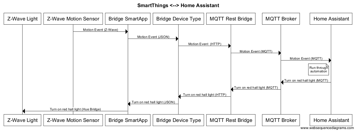
There are a lot of stops along the way for these events, but each piece is a simple translation layer to shuttle the events between systems.
This tutorial will take you through the steps to setup a dynamic DNS for your IP and allow trusted encrypted connection to it - for free using DuckDNS and Let’s Encrypt.
The DuckDNS part of this tutorial has no requirements but there are a few requirements as of now to run the Let’s Encrypt client.
The first step is to set up DuckDNS. This is a free dynamic DNS service that you can use to get a DuckDNS.org subdomain to point at your house. A dynamic DNS service works by having your home computer tell DuckDNS.org every 5 minutes what its IP is so that DuckDNS can make sure your domain name is set up correctly.
For this example we will assume our domain is hass-example.duckdns.org.
First step is to acquire and set up our domain name. For this, go to DuckDNS, log in with any of the supported login providers and add a domain. After this check out their installation instructions to finish your installation of DuckDNS. If you’re on a Raspberry Pi, see ‘Pi’ in the category ‘Operating Systems’.
Let’s Encrypt is a free, automated, and open certificate authority (CA). We will use this to acquire a certificate that can be used to encrypted our connection with Home Assistant.
Let’s Encrypt will give you a free 90-day certificate if you pass their domain validation challenge. Domains are validated by having certain data be accessible on your domain for Let’s Encrypt (they describe it better themselves).
Assuming that your home is behind a router, the first thing to do is to set up port forwarding from your router to your computer that will run Let’s Encrypt. For the Let’s Encrypt set up we need to temporary forward ports 80
(http connections) and 443
(https connections). This can be set up by accessing your router admin interface (Site with port forwarding instructions per router).
Now you’re ready to run Let’s Encrypt:
$ git clone https://github.com/letsencrypt/letsencrypt […] $ cd letsencrypt $ ./letsencrypt-auto certonly --email your@email.address -d hass-example.duckdns.org Updating letsencrypt and virtual environment dependencies....... Running with virtualenv: sudo /path/letsencrypt/bin/letsencrypt certonly --email your@e-mail.address -d hass-example.duckdns.org IMPORTANT NOTES: - Congratulations! Your certificate and chain have been saved at /etc/letsencrypt/live/hass-example.duckdns.org/fullchain.pem. Your cert will expire on 2016-03-12. To obtain a new version of the certificate in the future, simply run Let's Encrypt again. - If like Let's Encrypt, please consider supporting our work by: Donating to ISRG / Let's Encrypt: https://letsencrypt.org/donate Donating to EFF: https://eff.org/donate-le
If you’re using Docker, run the following command to generate the required keys:
sudo mkdir /etc/letsencrypt /var/lib/letsencrypt sudo docker run -it --rm -p 443:443 -p 80:80 --name letsencrypt \ -v "/etc/letsencrypt:/etc/letsencrypt" \ -v "/var/lib/letsencrypt:/var/lib/letsencrypt" \ quay.io/letsencrypt/letsencrypt:latest certonly \ --email your@e-mail.address -d hass-example.duckdns.org
With either method your certificate will be generated and put in the directory /etc/letsencrypt/live/hass-example.duckdns.org
. As the lifetime is only 90 days, you will have to repeat this every 90 days.
Before updating the Home Assistant configuration, we have to update the port forwarding at your router config. We can drop the port forwarding for port 80
as we no longer care about unecrypted messages. Update port 443
to forward to port 8123
on the computer that will run Home Assistant.
The final step is to point Home Assistant at the generated certificates. Before you do this, make sure that the user running Home Assistant has read access to the folder that holds the certificates.
http: api_password: YOUR_SECRET_PASSWORD ssl_certificate: /etc/letsencrypt/live/hass.example.com/fullchain.pem ssl_key: /etc/letsencrypt/live/hass.example.com/privkey.pem
You can now navigate to https://hass-example.duckdns.org and enjoy encryption!
Big thanks to Fabian Affolter for his help and feedback on this article.
]]>You could also do this with the automation component instead so whenever you put your house to sleep mode for example your Android device will open up Google Play Books or the Kindle app ready for you to read as well as dimming your lights, but this tutorial is all about the switches.
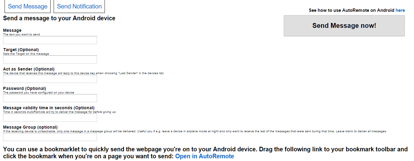
First things first you should install Tasker and AutoRemote onto your Android device and launch AutoRemote. You should see a URL above the QR code, visit it in your browser and it should bring up a page a bit like this.
Now type in SayOn
in the Message
box and you should see a box appear on the right with a URL in it, this is what we will be using in the Python script later on so save that for later. Do the same thing again but this time replace SayOn
with SayOff
. Now just click the Send message now!
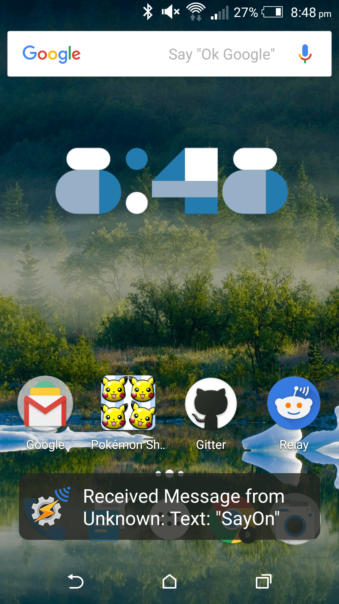
button to test that your commands will get sent to your Android device, if they do you will see a toast message at the bottom of your screen like this one.
Open up Tasker and make sure you’re in the PROFILES
tab, then select the plus icon to create a new profile. Select Event
-> Plugin
-> AutoRemote
-> AutoRemote
and then the pencil icon to configure the AutoRemote event. Select Message Filter
and enter in SayOn
then go back until it asks you for a task. Select New task
then just leave the next field blank and select the tick icon.
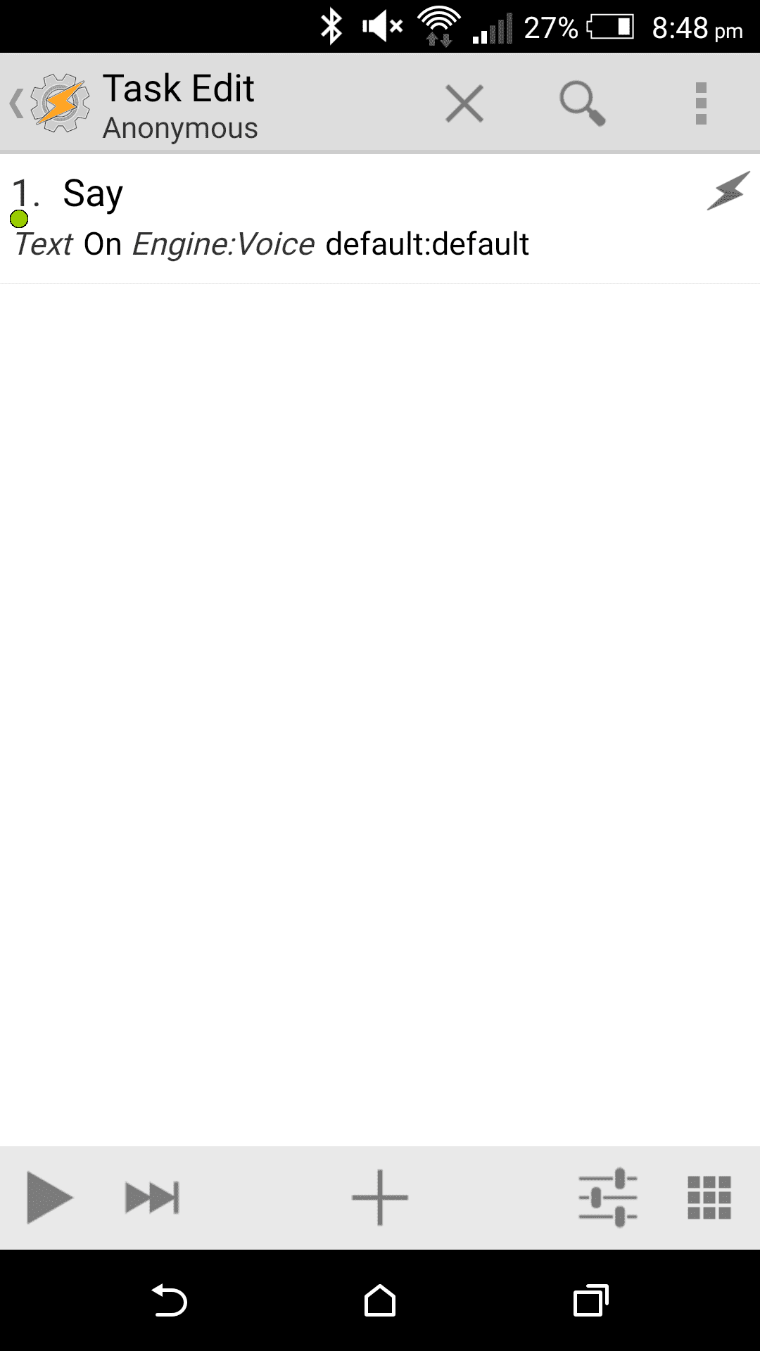
This is where we’ll configure our task, so select the plus icon to select an action. Select Alert
-> Say
to add a Say action. Enter On
in the text field and go back to test your task, make sure your media volume is up then select the play icon, you should hear your device say “On”.
Now you can go back to the main Tasker screen and create another profile but this time replace SayOn
with SayOff
and On
with Off
. After you’ve done that go to the main screen again and select the menu button at the top then Exit
and Save first
to make sure everything is saved properly.
Now it’s time to set it up the script, so create a new Python script and name it On.py
then enter this code:
import requests requests.get('[URL]')
Enter in your “On” URL then save it. Create another script but this time call it Off.py
and enter your “off” URL instead.
Add a command line switch to your Home Assistant configuration:
switch: platform: command_switch switches: tasker_say: oncmd: python "[LocationOfOnScript]" offcmd: python "[LocationOfOffScript]"
Now load up Home Assistant and whenever you toggle the switch you created your Android device will respond with either “On” or “Off”. :-)
]]>The influxdb
component makes it possible to transfer all state changes from Home Assistant to an external InfluxDB database.
The first step is to install the InfluxDB packages. If you are not running Fedora, check the installation section for further details.
$ sudo dnf -y install http://influxdb.s3.amazonaws.com/influxdb-0.9.5.1-1.x86_64.rpm
Launch the InfluxDB service.
$ sudo systemctl start influxdb
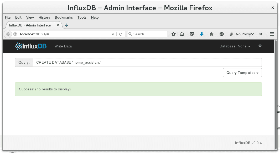
If everything went well, then the web interface of the database should be accessible at http://localhost:8083/. Create a database home_assistant
to use with Home Assistant either with the web interface or the commandline tool influx
.
InfluxDB web frontend
$ influx Visit https://enterprise.influxdata.com to register for updates, InfluxDB server management, and monitoring. Connected to http://localhost:8086 version 0.9.5.1 InfluxDB shell 0.9.5.1 > CREATE DATABASE home_assistant
An optional step is to create a user. Keep in mind to adjust the configuration (add username
and password
) in the next step if you prefer to go this way.
> CREATE USER "home-assistant" WITH PASSWORD 'password'
To use the influxdb
component in your installation, add the following to your configuration.yaml
file:
influxdb: host: 127.0.0.1
After you restart Home Assistant you should see that the InfluxDB database gets filled. The language to query the database is similar to SQL.
$ influx [...] > USE home_assistant Using database home_assistant > SELECT * FROM binary_sensor name: binary_sensor ------------------- time domain entity_id value 1449496577000000000 binary_sensor bathroom_door 0 1449496577000000000 binary_sensor bathroom_window 0 1449496577000000000 binary_sensor basement_door 0 1449496577000000000 binary_sensor basement_window 0 1449496684000000000 binary_sensor bathroom_window 1 [...]
Grafana is a dashboard that can create graphs from different sources including InfluxDB. The installation is simple, and there are detailed steps for many different configurations on the Grafana installation page. For a recent system that is running Fedora:
$ sudo dnf -y install https://grafanarel.s3.amazonaws.com/builds/grafana-2.5.0-1.x86_64.rpm
Start the grafana server.
$ sudo systemctl daemon-reload $ sudo systemctl start grafana-server $ sudo systemctl status grafana-server
Login with the username admin
and the password admin
at http://localhost:3000/login. Now follow the InfluxDB setup instructions.
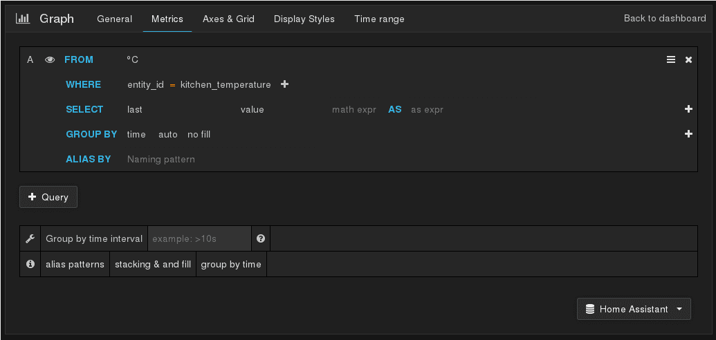
Now you can start to create dashboards and graphs. You have various options to get the data from the graph. The next image just shows a screenshot of the setting for a temperature sensor.
Grafana settings
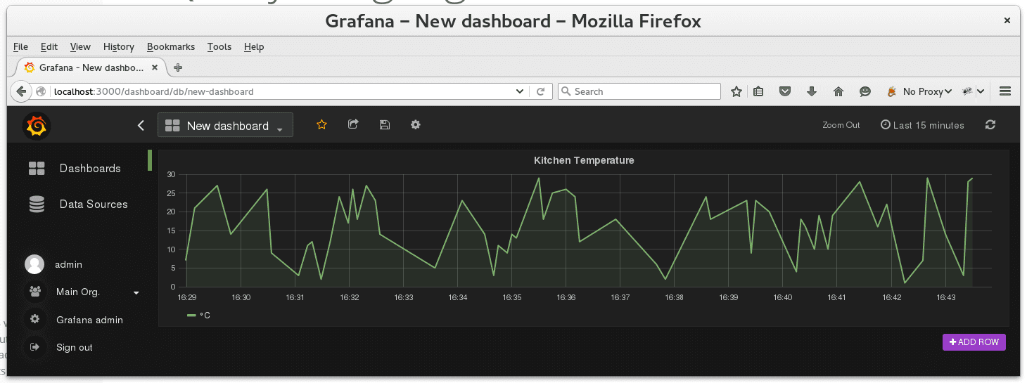
If the graph is not showing up in the dashboard you need to adjust the time range in the right upper corner. The graph is created for all state changes recorded by Home Assistant.
Grafana Temperature graph