| .. | ||
| .gitignore | ||
| bottom.png | ||
| esp8266-button-cache.lib | ||
| esp8266-button.kicad_pcb | ||
| esp8266-button.net | ||
| esp8266-button.pro | ||
| esp8266-button.sch | ||
| README.md | ||
| top.png | ||
ESP8266-button PCB
The PCB schematics and layout of the ESP8266-button made with KiCad.
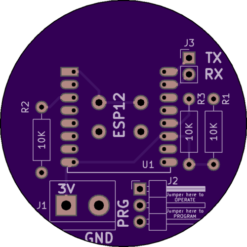
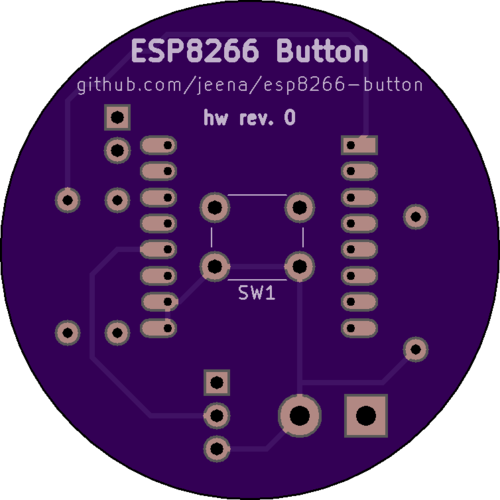
Board render
Top
Bottom
Components
- ESP12 WiFi module
- 3 x 10KΩ resistors
- Screw terminal (5.08mm)
- Tactile on/off switch (6x6mm)
- 3-pin male angled header
- 2-pin male or female straight header
- Pin jumper (2.54mm pitch)
KiCad Libraries
For full source code modifiability please import the following libraries which were used for the symbols and the footprints of this project: